
Show us your Engine bay


Join Date: Feb 2008
Location: Cap Pele, New Brunswick, Canada
Posts: 315
Likes: 0
Received 0 Likes
on
0 Posts
Senior Member
Join Date: Jul 2009
Location: Central South Carolina
Age: 69
Posts: 5,997
Received 503 Likes
on
429 Posts
My $0.02 worth (for those who know [or don't know] but seem to be troubled consistantly, given what they install/say).
Cold air intake - Wikipedia, the free encyclopedia
I see a few actual CAI systems WITH FILTERING in this entire thread. Properly done, an actual CAI (filtered without reduced cross-sectional tubing intake reduction, and/or insulated enough to have an actual reduction in intake air temperature) as being beneficial for any of our cars. I actually only remember seeing one member post the actual drop in his intake air temperature in this entire thread. Even if it is properly documented, a one degree reduction is on the correct side of gains. Higher intake temps are on the wrong side. Please don't tell me the openings of the conical filters are lined up with the support openings and are getting their airflow from that. The air will flow the least restriction which is the majority of the cross-sectional area of the filter material around the outside of the cone. Even if you place/port the inner central opening through the support, airflow dynamics dictate the less restrictive outer filter paper in the engine bay will flow much more than the inner coned tube flow that you ran through the rad. support. The most accurate data is actual before/after temperatures (same temperature sensor location and specific rpm numbers (and) denoted whether or not the vehicle was being driven while monitoring or standing still and monitoring).
Anything else is subjective at best, or harmful at worst.
There, I said it! I stick by it as well. Those who crucify members who point that out need to review exactly what a CAI is, or is not. Shooting the messenger doesn't promote dissemination of accurate information to everyone. I will not be baited into responding to anyones comments, as I am sure a boatload will pip in their $0.02 worth either agreeing with me, or flaming me.

I think it may have been me who posted reduced IAT as per measurement with the OBDII sensor. The one the ECU uses for engine management. It was a true A-B-A-B test. Same day, over a 1 1/2 hour period, same outside temp (as per the dash temperature gauge).
I drove down the interstate for a 30 mile round trip, monitoring the outside and IAT readings, returned home and swapped out the OEM/K&N setup and installed my home-built CAI. Ran the same course and repeated the test, ending up with the CAI installed.
75 MPH
OEM/K&N
Outside Air 84-86 deg F.
IAT (stabilized) 112-115 deg F
75 MPH
CAI
Outside Air 84-86 deg F
IAT (stabilized) 99-102 deg F
Stopping for even a brief time sent both setups into the 125 deg F range. The CAI seemed (not measured) to recover quicker. Less thermal mass.
Any questions?
Senior Member
Join Date: Jul 2009
Location: Central South Carolina
Age: 69
Posts: 5,997
Received 503 Likes
on
429 Posts
You said the OEM temps at idle was the same vs your CAI (are those metal tubes or chromed plastic)? You mentioned they climbed into the 125 F range, was that with any type of tail breeze (it matters, engine heat easily flows forward into the OEM/CAI placed ducted area through the radiator/condensor coils and various gaping holes in that bulkhead if the breeze is towards the front)? I would expect that influx of (engine bay heated) air being sucked into those two intake points if the prevailing breeze carried that heat forward. Just a thought?
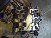
Finally, yes I keyed on your post. I did that because its rare to find that type of information posted unless someone asks. Yours is the example I liked most because of the information given, and the effectiveness of the design of actual CAI's. Not to mention (but I will anyway), its absolutely gorgeous looking! Clean, sharp, and in my opinion as pictured, totally 100% functional and a correct application of a CAI.
Originally Posted by GraphiteGhost
You said the OEM temps at idle was the same vs your CAI (are those metal tubes or chromed plastic)? You mentioned they climbed into the 125 F range, was that with any type of tail breeze (it matters, engine heat easily flows forward into the OEM/CAI placed ducted area through the radiator/condensor coils and various gaping holes in that bulkhead if the breeze is towards the front)? I would expect that influx of (engine bay heated) air being sucked into those two intake points if the prevailing breeze carried that heat forward. Just a thought?
Finally, yes I keyed on your post. I did that because its rare to find that type of information posted unless someone asks. Yours is the example I liked most because of the information given, and the effectiveness of the design of actual CAI's. Not to mention (but I will anyway), its absolutely gorgeous looking! Clean, sharp, and in my opinion as pictured, totally 100% functional and a correct application of a CAI.
has anyone ever related to you the truism:
The best indication of a mans' intelligence is the degree to which he agrees with you?
Mine is all metal. 3" OD. Unfortunately, the y-pipe is .060" stainless steel and has more thermal mass than I would like. If I could have made this whole thing out of Boron, I would have. The balance of the materials is aluminum and silicone (couplers and reducing elbow). The intake tubes are .030" wall, silicone smoothwall flex, 3.00" ID and is jammed through the radiator bulkhead. It fits well on the passenger side but is really crammed into the driver's. This is where Needswings and TVT use a 2.75" tube. I was able to deform mine to fit. Barely. There is a 12% difference in measured cross sectional area. Not perfect, but the best I can do. Even on the passenger (larger) side, there is a slight deformation from a true circle. As anyone who passed 8th grade geometry can tell you-any deformation of a circle reduces the area (cross section). Right?
As to having a tailwind at rest? He!!, I drive roadster! After a 30 mile cruise, I could be in the vortex of a tornado and not know it. No idea, but your point is well taken, just not considered at the time.
Your point of linearizing the airflow before ingestion by the MAF is a point I considered and designed around. Removal of the inlet screens has been asked about and bandied about here in many threads. Sure, one will gain maybe 5%-10% greater cross section, but it will confuse the MAF at higher airflow volumes. Laminar airflow has been well understood since Bernoulli figured out how an asymmetrical surface can produce lift.
For those reading this: Picture if you will a faucet with the aerator removed; as you start flow, you see a v-shaped cross section of water steam. As you increase the flow rate, the shape of the water flow stays the same, but moves at a less oblique angle. If you had a stationary object in the flow, it would only be hit dead-center by the stream at a certain pressure/flow. Replace the aerator. Now, no matter the flow rate, it all comes out at the same angle, in a uniform cross section. Needswings got around this by re-positioning the MAF at the end of a long (~12") section of straight run tubing: the flow/pressure is isobaric
(same pressure) across its face.
And at the same time removed any restriction in the OEM throttle body. And the linearizing screens.
Nice thinking Needswings and/or TVT and all who contributed!
I just wasn't willing to pay the MSRP for the product.
Please rebut?
Max
Senior Member
Join Date: Jul 2009
Location: Central South Carolina
Age: 69
Posts: 5,997
Received 503 Likes
on
429 Posts
My reason for asking about the metal vs plastic in the intake path was because of the thermal activity inside the engine compartment during idle, at rest. Having the cooler intake air BTU's migrate into those metal components (cold to hot) is annoying but thats physics/thermal dynamics! Yes, most of the time its moving down the road and that period of time there is only some minimal thermal influence, its just I was trying to understand your results better (125 F at idle IAT). Also, the recovery may be quicker (your note that it seemd to recover sooner) with your CAI as installed (but then we do have all that thermal energy in that metal don't we?). I know it would be time involved to check recovery with both systems (OEM/CAI), but if you ever get bored someday, it would be nice to know. Personally, if I install one, I would be looking for something less 'thermal' retentive (as opposed to **** retentive), unless I just wanted the look and didn't care about the resuls of that questionable thermal influence. Given what I just mentioned, it (the non-metal tubing) would have to follow the plan of 'larger-to-smaller' from those bulkhead supports to the throttlebody (like yours does). I do not want any (intake) air compression after those rather small openings next to the radiator, all the way to the MAF opening. After that MAF, its back on the MB engineers (here's hoping they did ALL their calcualtions, arent we?). Oh, did you measure the cross-sectional openings (at those radiator bulkhead openings) when you had everything apart? I would guess they are @ 105%(+/-) total volume above the MAF opening (just a WAG).
No rebutal, just idle banter between XF owners?
Edit added the "(at those radiator bulkhead openings)" 2nd para., 2nd to last sentence.
Last edited by GraphiteGhost; 07-25-2010 at 12:53 AM.
Originally Posted by patpur
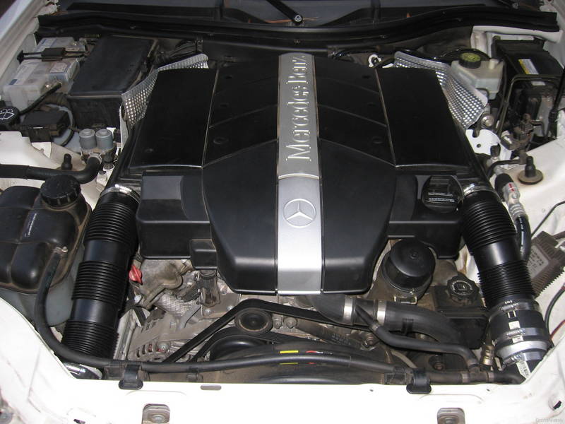
Lets see if this works. Here's mine. I went for less bling, little more subtle look.
All covers have been fleck/texture painted. I'm not finished with the engine cover but for now it's black texture painted.
All covers have been fleck/texture painted. I'm not finished with the engine cover but for now it's black texture painted.
Originally Posted by patpur
Same cover is on our 04 c240 4 matic. I think FP and several others use this one. If you get stuck on a part number pm me. I know my wifes cover fits, I tried stealing it but she found me out!
Here's mine:
Note: I'll have to repaint it.... as soon as I learn to paint.
")
Last edited by LGV-XFIRE; 08-22-2010 at 09:13 PM.
Senior Member


Originally Posted by patpur
Lets see if this works. Here's mine. I went for less bling, little more subtle look.
All covers have been fleck/texture painted. I'm not finished with the engine cover but for now it's black texture painted.
All covers have been fleck/texture painted. I'm not finished with the engine cover but for now it's black texture painted.
Where did you get the cover and those intake pipes?
Join Date: Jul 2007
Location: Dallas, the Republic of Texas
Age: 64
Posts: 7,951
Likes: 0
Received 9 Likes
on
9 Posts
Originally Posted by coolZero
Where did you get the cover and those intake pipes?
Originally Posted by InfernoRedXfire
The intakes are Needswings.